


- Browse Categories
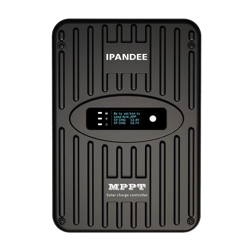
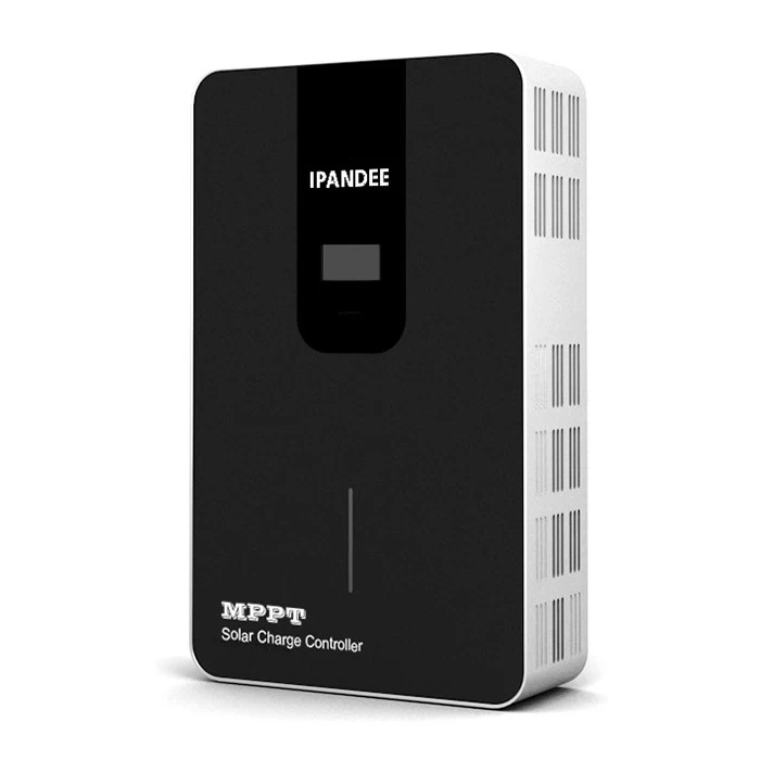
- EMMPT48 series MPPT solar charge controller
- The Explorer-NS series MPPT solar charge controlle
- MPPT solar charge controller eSmart4
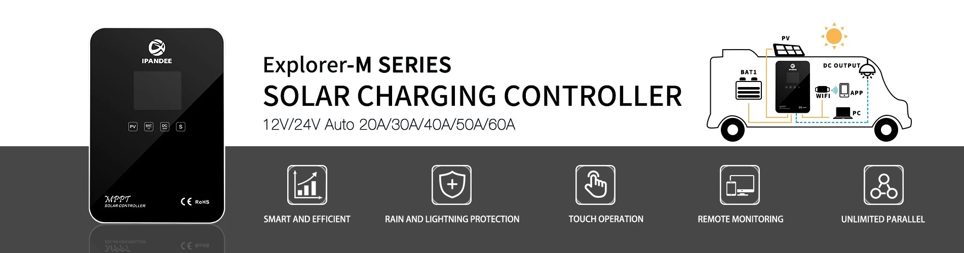
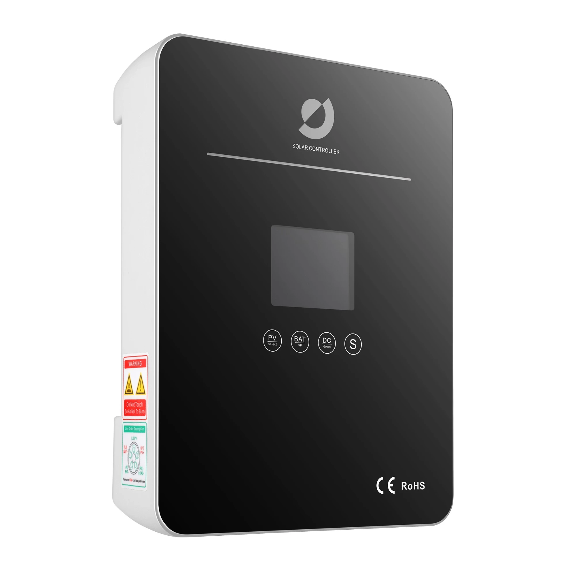
- EXPLORER-M MPPT Solar Smart Digital Controller
- EXPLORER MPPT Solar Smart Digital Controller
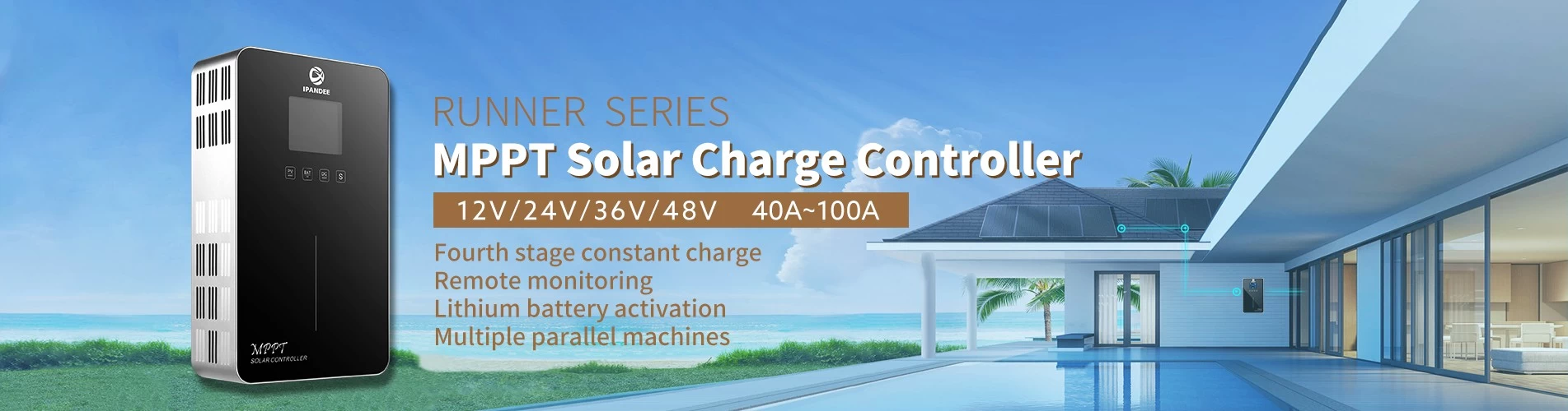
- RUNNER MPPT Solar Smart Digital Controller
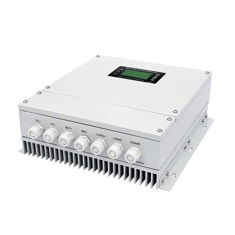
- GALAXY high power series MPPT solar controller
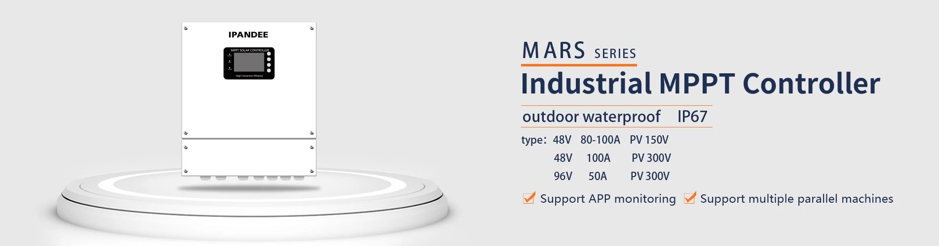
- MARS outdoor series MPPT solar controller
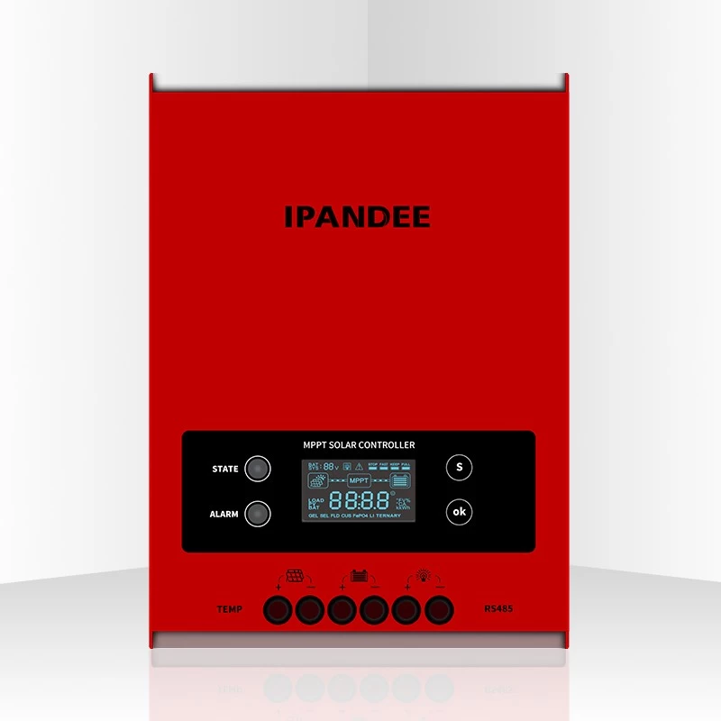
- eSMART series MPPT solar controller
- MASTER series MPPT solar controller
- Accessories
- (out of product)WISER series MPPT solar controller
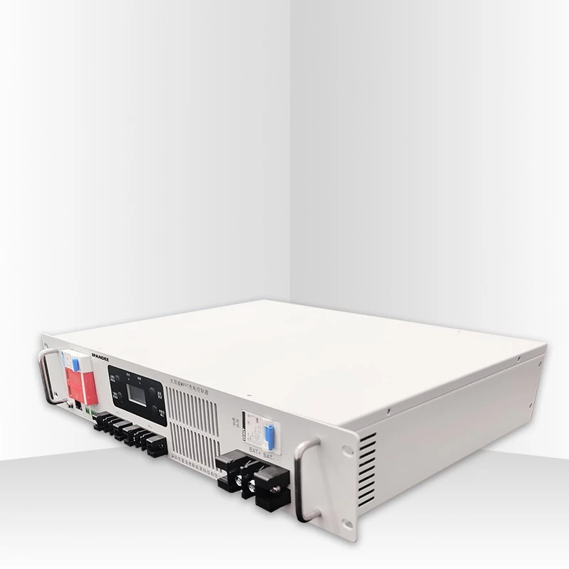
- (out of production)Inverter SP Series 350W-20000W
- (Has been removed)
- (out of production)I-Panda SPC Series Inverter
- Certifications
-


")


- Subscribe
-
Get email updates on new products
- Hot Products

- Contact Us
-
Tel: + 86-755-23091101&+86-755-23091100
Fax: + 86-755-23091102
Information: info@ipandee.com
address: Floor 2, building A2, LiLang Software Park, No. 31, Bulan Road, Nanwan street, Longgang District, Shenzhen
China Post code: 518000 Contact Now
- Follow us
- News
-
-
Why is the inverter starting voltage higher than the minimum voltage?
In the photovoltaic grid-connected inverter, one parameter is strange, that is, the inverter input starting voltage. This voltage is about 30V higher ... -
How to solve the AC inverter overvoltage problem?
just nowPhotovoltaicOn-grid power generation is becoming more and more popular, and ordinary people's homes can see PV power plants in real time. Howe... -
The difference between an improved sine wave and a pure sine wave inverter
This article describes the difference between an improved sine wave and a pure sine wave inverter. ModifiedSine Pure Wave: The most common general pur... -
Europe's first waste photovoltaic panel recycling plant
Solar panels have a service life of 20 to 30 years. Along with the mass production of the global solar energy manufacturing industry in the past few y... -
The world's top ten PV inverter companies
The inverter is also called the power regulator. According to the use of the inverter in the photovoltaic power generation system, it can be divided i... -
Why should the inverter stop working when the grid is out of power?
Some people install a photovoltaic system, they will have a mentality of "even if the power grid is cut off, if there is a sun, and their homes can us... -
What is the difference between MPPT function and solar inverter without MPPT function?
The MPPT controller utilizes maximum power point tracking technology to extract the maximum power from the solar array to charge the battery. The maxi... -
Scientists have discovered that sand can make solar cell silicon materials
According to a report by the Kyodo News Agency on November 6th, visiting professors of the University of Tokyo, Sugawara, and others opened a joint st... -
Domestic energy storage market competition pattern
Energy storage as a new market for many battery manufacturers in China andInverterVendors bring the opportunity to expand new affairs and change the p... -
Portugal will achieve 100% renewable energy supply in 2050
Portugal's Minister of Environment and Energy Transformation João Pedro Matos Fernandes revealed that Portugal will achieve its carbon neutrality tar...
-
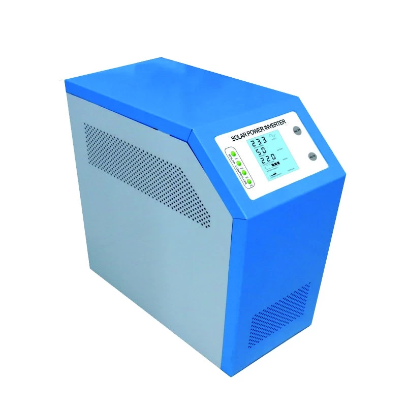
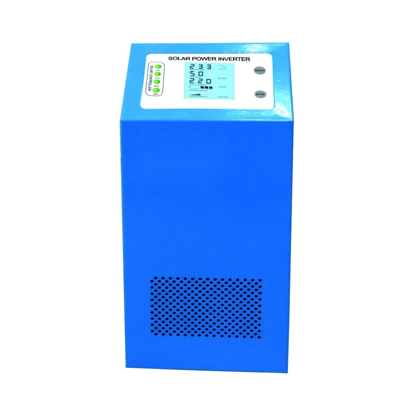
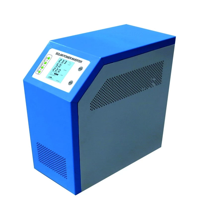
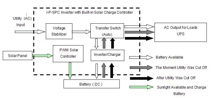
I-Panda 350w controller and inverter series SPC hybird
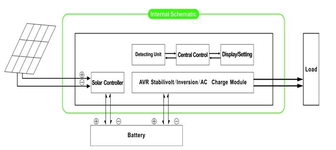
- Component
- 1) Pure sine wave inverter low-frequency high-quality (utility charge
- function and UPS function)
- 2) Built-in solar charge controller PWM
- Application
- 1) solar power system off-grid
- 2) Solar system with grid power as a complementary
Features
1)Easy to install. To set up a solar system, customers simply plugwith solar panels and batteries.
2) CPUmanagement and control, modular design
3) LCDscreen, can visually display different parameters (such as output voltage,frequency, operating mode, etc.)
4) Multifunctiondesign, customers do not need to buy solar controller, charger, stabilizer, etc.
5)Connecting the external battery to extend the time convenient backup power; user canconnect as many batteries as needed according to local sun and light wind.
6)Great capacity and high capacity, this series of & amp; nbsp; Investors can not only lead resistance load;but also various types of inductive loads such as engine, air conditioning,electric drills, fluorescent lamps, gas, etc. It can handle almost any typeLoad
7) Undercircuit design frequency pure sine wave, good system stability, easy tomaintenance, low failure rate and long service life (in proper operation,It can be as long as five years)
8)Perfect protection: protection of low voltage, over voltage protection, overheatprotection, short circuit protection, overload protection
9)CE / EMC / LVD / RoHS / EMC approvals CCC
10)2 year warranty, technical supports lifelong
Function
1 Sole investment function in the reverse mode (only connected to the battery), & amp; nbsp; can be set in the normal operating modeand sleep mode
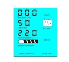
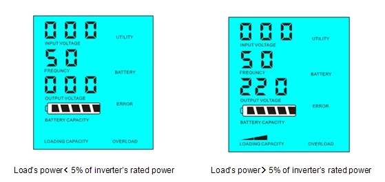
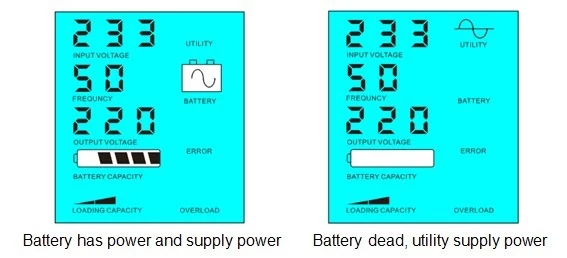
1.1 & amp; nbsp; Normal working mode: FREQUENCYon the LCD screen is set to 01 No matter if AC loads connectedinvestor or not, the inverteroutput terminal voltage will always be ready to supply power to the loads.In this mode, the LCD screen will display as below:
1.2 & amp; nbsp; Sleep mode: FREQUENCYon the LCD screen is set to 02. If power loads that are connected tothe investor is less than 5% of Inverterrated power, there is no output of the inverter. That is, onlychip inverter is working in these conditions and energy consumptionit's just 1-6W; If the power of the loads connected to the inverter isthan 5% of the rated power of the inverter, the inverterautomatically starts the role of investment and supply power to the loads within5s. As shown below:
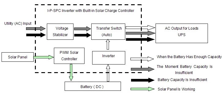
Systemintroduction in this way:
1)Only the solar panel charges the battery
2)Unique independent off-grid solar system; suitable for areas that are & amp; nbsp; & Amp; nbsp; & Amp; nbsp; & Amp; nbsp; & Amp; nbsp; lack of utility or are rich in solar energy
Two.UPS useful function underMode dad (connected tobattery and utility) can be useful to establish a principle, standby battery andBattery first standby useful.
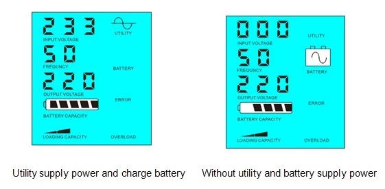
2.1.Utility first UPS battery standby mode: the LCD frequency is set to01 When both the utility and the battery are connected to the inverter, utility willsupply power to the loads before the battery. When the utility is cut, thebattery to supply power automatically continue after the investment.
StepsThey are:
Step1: When power is available, it will be output immediately after stressstabilized and battery charging at the same time.
Step2: When the power fails suddenly, the inverter converts DCthe AC automatically to ensure uninterrupted power supply within 5ms.
Step3: When power becomes available again, it will automatically transferutility to supply power to the loads and charge batteries simultaneously.
ViewWorkflow as follows:
LCDappears as bellow:
Systemintroduction in this way:
1)There are 2 ways to charge the battery, utility and solar panel
2)This system is suitable for power systems constructed in areas without utility orpropulsion systems that are frequently used in areas with / without utility
2.2.Battery first, expected utility UPS mode: frequency on the LCD screen is set to03. & amp; nbsp; When both the utility and battery areconnected to the inverter, battery will supply power to the loads beforeutility. When the battery capacity is not enough, utility will continue to deliverpower automatically.
StepsThey are:
Step1: When the battery has sufficient power, that will power loads directly
Step2: When the battery has sufficient power, will be automatically transferred toutility supply power to loads
Step3: After the battery is fully charged (eg by solar or wind loadcontroller), it will then automatically be transferred to the battery power supplyloads.
ViewWorkflow as follows:
LCDappears as bellow:
Systemintroduction in this way:
1)There is only one way to charge the battery: Solar panel
2)This system is suitable for areas where electricity is expensive andenvironmental areas where solar energy can be fully used to conserve power network,as solar Family & amp; amp; wind system and solar lantern & amp; amp; Wind system
Parameter
|
Mode |
500VA |
||
|
Nominal Output Capacity |
350W |
||
|
Pico Power |
700W |
||
|
Battery Voltage (DC) |
12V or 24V |
||
|
PWM Solar controller |
Voltage |
12V or 24V |
|
|
Actual |
10A |
||
|
Max PV Input Voltage |
12V System: 25V |
||
|
24V System: 50V |
|||
|
Size W x D x H (mm) |
335 * 165 * 375 |
||
|
Packing Size W x D x H (mm) |
355 * 185 * 395 |
||
|
Net Weight (kg) |
7 |
||
|
Gross Weight (kg) |
8 |
||
|
General Parameter |
|||
|
Work (Selection) Mode |
1 |
Utility First, standby battery |
|
|
2 |
Dream Similarly, no utility power load exceeding 5% of the nominal power, start working automatically |
||
|
3 |
Battery first pending utility |
||
|
AC Entrance |
Voltage |
220 V ± 35% or 110V + 35% (Optional) |
|
|
Frequency |
50Hz ± 3% or 60 Hz ± 3% (Optional) |
||
|
AC Exit |
Voltage |
220V ± 3% or240V or 230V ± 3 ± 3% or ± 100 V or 110 V 3% ± 3% (Optional) |
|
|
Frequency |
50Hz ± 0.5 or 60 Hz ± 0.5 (Optional) |
||
|
Utility Receivables |
AC Charging current |
0 ~ 15A |
|
|
Load Time |
It depends Capacity and quantity of battery |
||
|
Battery Protection |
Automatic detection, protection for loading and unloading, Intelligent Management |
||
|
PV Load |
Total PV input current must be less than the rated current |
||
|
Display |
Display Mode |
LCD + LED |
|
|
Display Information |
Entrance voltage, output voltage, output frequency, battery capacity, state of charge, state information |
||
|
Exit Wave mode |
Pure sine wave output, rate≤3 waveform distortion |
||
|
Overload Skill |
& Gt; 120% 1 min, & gt; 130% 10s |
||
|
Power Consumption |
Dream Mode |
1 ~ 6W |
|
|
Normal Mode |
1 ~ 3 |
||
|
Conversion Efficiency |
80% ~ 90% |
||
|
Transfer Time |
& Lt; 5 ms (AC to DC / DC to AC) |
||
|
Protection |
Overload output short circuit, high voltage input, low input voltage, overheating |
||
|
Environment |
Temperature |
-10 ℃ ~ 50 ℃ |
|
|
Humidity |
10% ~ 90% |
||
|
Altitude |
≤4000m |
||
- The above parameters with "o" means that the parameter has to do factory settings according to customer preference.
- We have our own professional driver and UPS inverter R & amp; amp; D and provide technical support and OEM service.
- The information above is the standard parameter controller of our company can be changed according to customer's requirement.
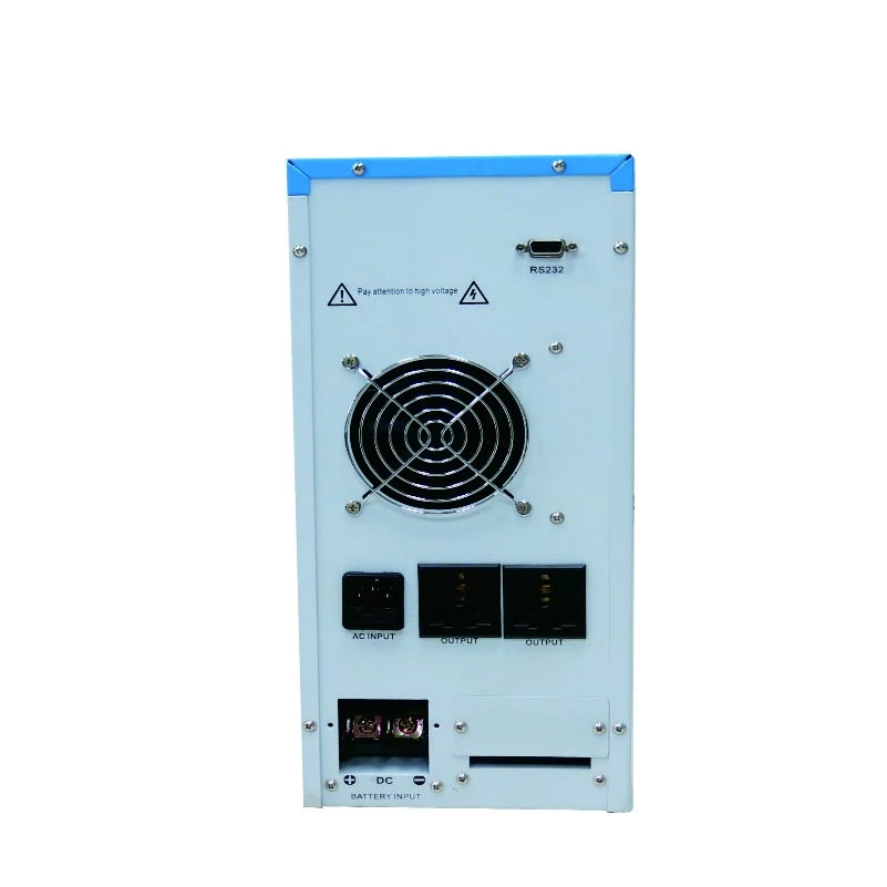
ConnectionDiagram

Other
Pleasesee the outline design, technical documents, product brochures, etc
Madeby the Department of Engineering, May 5, 2014, 1st Edition
Tel:+86-15002089033
Contact Person:Henry Feng
PDF Show:PDF


