



















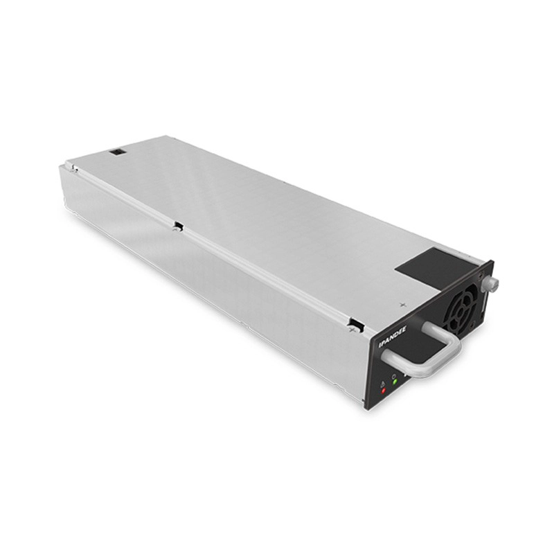
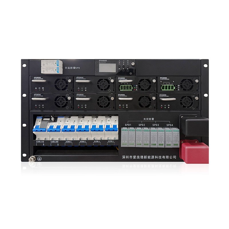
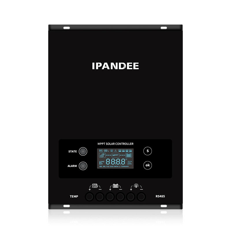
- 1.Where can I review the products parameter and manual before purchasing?
- 2.Can you provide OEM or ODM service for customers?
- 3.Can MPPT charge controller charge lithium battery? How to set it?
- 4.How to set up the parameter to charge lithium battery?
- 5.Is there a setting on the controller to tell it whether the batteries are sealed lead-acid or gel?
- 6.If the bulk charge voltage is 14.7V, does the charging voltage is the same 14.7V or other lower voltage?
- 7.Could i charge my golf cart acid battery with your MPPT controller?
- 8.After shut down and restarted MPPT controller, will the setting parameters keep retain or revert to default setting?
- 9.When the solar panels charge the battery through a mppt controller, and with DC load output at the same time, does the load using energy from solar panels or from battery?
- 10.What is the minimum PV panel input voltage? Why does it recurring “charge-stop-charge-stop” situation?
- 11.Could i monitor the MPPT controller through a PC?
- 12.Where can i get the APP for the WiFi module connection?
- 13.Why connect the RS485 cable with controller and can not see it on my computer?
- 14.Will the RS485 cable allow to communication between 2 controllers in parallel?
- 15.Can it be connected with another controller to charge battery bank?
- 16.Is this a positive or negative ground controller?
- 17.If i charge my lithium battery with Wiser or eSmart MPPT controller, could i must be used RS485 cable and WIFI module?
- 18.How can we get the technical support for products?
- 19.Can the products be installed and used outdoors?
- 20.What size and model of the cable is required to connect input and output terminals?
- 21.MCJ Solar Hybrid Controller Common Issues and Troubleshooting Methods
- 22.How to choose a MPPT controller?
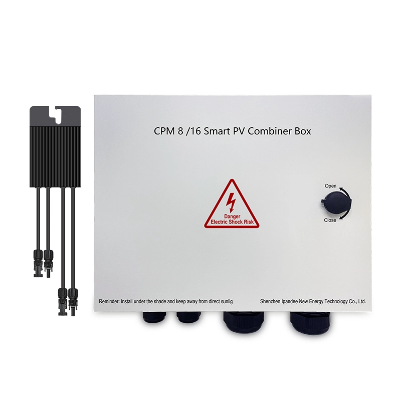
- 23.Troubleshooting Common Issues with IPANDEE Combiner Box Adapters
- 24.How to make maximum efficiency use of the solar panels in series-parallel connection?
- 25.Troubleshooting Common Issues with IPANDEE Controllers
- 1.Where can I review the products parameter and manual before purchasing?
-
A1: Related files can be found through through official website - Download.
- 2.Can you provide OEM or ODM service for customers?
-
A: Yes. Customers should provide formal Letter of Authorization. We will keep our partnership strictly confidential and customized products will be not sold to any third party.
- 3.Can MPPT charge controller charge lithium battery? How to set it?
-
A: Yes. All series controllers can set up “User-defined” battery type for lithium battery by APP or PC software. Galaxy, Master, Mars series can be reset battery type on controller itself, too.
- 4.How to set up the parameter to charge lithium battery?
-
A:At present, the MPPT controller charging is mainly designed for the traditional conventional battery pack (12V is composed of serial and parallel series), and the battery system is automatically identified according to the battery voltage. Therefore, if the lithium battery pack needs to be charged, it needs to be converted into a conventional battery. Group, the conversion method is as follows:
The nominal voltage of the lithium battery pack is between 9~15V, just like the 12V conventional battery pack, the internal calculation ratio is=1;
The nominal voltage of the lithium battery pack is between 18~30V, just like the 24V conventional battery pack, the internal calculation ratio is 2;
The nominal voltage of the lithium battery pack is between 32~40V, just like the 36V conventional battery pack, the internal calculation ratio is 3;
The nominal voltage of the lithium battery pack is between 42~60V, just like the 48V conventional battery pack, the internal calculation ratio is 4;
The nominal voltage of the lithium battery pack is between 72 and 120V, just like the 96V conventional battery pack, the internal calculation ratio is 8;
The nominal voltage of the lithium battery pack is between 144~240V, just like the 192V conventional battery pack, the internal calculation ratio is 16;
At the same time, there are two main parameters for battery charging, one is the main charging voltage value and the other is the floating charging voltage value; so please check the main charging voltage value of the lithium battery pack first, and the lithium battery pack has no floating charging pressure value, so it is recommended Set the float voltage value ≤ main charge voltage value -- (0~0.3V)
For example, the parameters of a user's lithium battery pack are as follows: the nominal voltage is 48.1V (consisting of 13 3.7V cells in series), and the maximum charge cut-off voltage is 54.6V (4.2V*13) (this parameter refers to Main charging voltage),
The steps for setting the MPPT controller parameters for the lithium battery pack are:
1). Calculate the conventional battery pack corresponding to the lithium battery pack, and the internal calculation ratio; 48.1V is between 42~60V, just like the 48V conventional battery pack, the internal calculation ratio is 4;
2). Set the battery type to Custom Type User defined
3). Set the main charging voltage value = 13.65V (54.6V/4=13.65V; internal calculation magnification = 4)
4). Set the float voltage value between 13.33 and 13.65; (the main charge voltage is 13.65V-(0~0.3V)
The above settings can be made by the host computer, WiFi module, or controller (requires the model that can be set) - 5.Is there a setting on the controller to tell it whether the batteries are sealed lead-acid or gel?
-
A: Yes, all of our MPPT charge controller can be checked and set up the conventional battery types (Sealed/Gel/Flooded) by LCD screen, APP and even PC software.
- 6.If the bulk charge voltage is 14.7V, does the charging voltage is the same 14.7V or other lower voltage?
-
A: When the bulk charge voltage of battery is set to 14.7V, the MPPT controller charge voltage will also be control within the range of 14.7V. It will charged the battery in three stages through constant current charge mode CC → constant voltage charge mode CV → floating charge mode CF.
In CC mode, the charging voltage is equal to the battery voltage; In CV mode, the charging voltage is equal to the bulk voltage set value of 14.7V; In CF mode, the charging voltage is equal to the floating voltage set value, like 14.5V. - 7.Could i charge my golf cart acid battery with your MPPT controller?
-
A: Yes, you can set the MPPT controller charge parameter according to the specific charging parameters of golf cart acid battery (such as the bulk voltage and floating voltage value).
- 8.After shut down and restarted MPPT controller, will the setting parameters keep retain or revert to default setting?
-
A: All of our MPPT charge controller have storage memory function, it will keep the original setting parameters after shut down and restart.
- 9.When the solar panels charge the battery through a mppt controller, and with DC load output at the same time, does the load using energy from solar panels or from battery?
-
A: The energy using will be given priority from solar panels. If the solar panel is underpower, that will powered by batteries. For example the load need 50A, the solar panel generates is 30A and supplement from battery is 20A.
- 10.What is the minimum PV panel input voltage? Why does it recurring “charge-stop-charge-stop” situation?
-
A: Each MPPT controller has start charge voltage point. Only if the PV voltage is higher than the start charge voltage point can be charged. When the PV voltage is less than the low voltage protection point, it will stop charge. The “charge-stop-charge-stop”situation is easy to recurring if the PV voltage is close to the charge voltage start point, especially in the morning or at nightfall. It will also recurring the same situation if the system is in strong sunshine, so we suggest increase the number of solar panels in series when PV working voltage is lower.
- 11.Could i monitor the MPPT controller through a PC?
-
A: Of course, connect the MPPT controller and PC through a RS485 cable, and install the PC software program on the computer. Please ensure the communication cable is purchase from the same dealer.
- 12.Where can i get the APP for the WiFi module connection?
-
A: Three methods are available :
1)Scan the QR codes from the WIFI module user manual;
2)You can search “MyGreen SolarMonitor” in iPhone app store and Google Play to get the APP. In domestic with Android is download from Tencent app;
3)Get the APP download program from salesman. - 13.Why connect the RS485 cable with controller and can not see it on my computer?
-
A: Precautions before connecting:
1)Make sure the RS485 communication cable (applicable to any of our MPPT controller) is our configuration product. (Note: Because the accessories protocols used by different manufacturers
are different, they are basically not universal, including the meter, WiFi module, etc.)
2)Compatible Windows system: Windows XP; Windows VISTA; Windows2003(32-bit & x64-bit); Windows2008(32-bit & x64-bit); Windows 7 (32-bit & x64-bit); Windows8 (32-bit & x64-bit); Windows10 (32-bit & x64-bit)
Installation Steps:
1.Please make sure the communication cable and controller are from the same manufacturer.
2.Please install MY GREEN SOLAR MONITOR PC software in your computer(software hyperlink)
https://www.dropbox.com/s/n9qnywqq2zajh4s/install_MyGreenSolarMonitor_CS_Windows.exe?dl=0
3.Install MPPT controller to the off-grid solar system. Please make sure that the MPPT controller is working normally (the controller will automatically power on after it is connected to the battery)
4.Well-connect the computer and controller through RS485 communication cable. Double-click the PC software icon to launch the software. The Com.port will auto-match the PC COM, the other parameters are displayed by default, no need to change. Then click the button”Apply”. In 5S, start real-time monitoring of system overview, trend graph and data information.
5.If the PC software cannot display the system running status, please check whether the exclamation mark appears on COM.Port in your computer ”device manager”. If so, please click the right mouse button and follow the operation steps to remove it.
If above still cannot solve to connection, recheck the operation steps again please and contact the salesman at the same time. Because all the products need have rigorous testing and ensure the qualified before delivery. - 14.Will the RS485 cable allow to communication between 2 controllers in parallel?
-
A: For Wiser and eSmart series MPPT controller only has one RS485 port can be used for single-machine connection communication. (Like PC software and WIFI module). They cannot connect in parallel or intercommunication use.
Galaxy, Master, Mars, Explorer, Runner series MPPT with two RS485 port can be used for series and parallel. (Please note: As long as the controller can be used in parallel, it can also parallel operation in different series or models.) - 15.Can it be connected with another controller to charge battery bank?
-
A: Our MPPT charge controller cannot charge the battery bank with other brand MPPT or PWM controller. If need multiple controller to charge one battery bank, please purchase the same model controller which can in parallel use. (For example Galaxy, Master, Mars, Explorer, Runner series MPPT controller)
- 16.Is this a positive or negative ground controller?
-
A: Wiser and eSmart series MPPT controller is design for common positive and can use in positive ground. Please note they must be installed and used under professional operation, otherwise there will be personal safety hazards. Whether the off-grid solar system is common positive or negative ground use is depends on the design requirements of the project.
From the safety point of view, we do not suggest the system use in common positive or negative ground, which is not involved to this aspects . - 17.If i charge my lithium battery with Wiser or eSmart MPPT controller, could i must be used RS485 cable and WIFI module?
-
A: Yes, because Wiser and eSmart series only can set the battery type, cannot set the specific parameter by itself. The specific charging parameter must be set through PC software (need purchase RS485 cable) and APP (need purchase WIFI module) if need.
- 18.How can we get the technical support for products?
-
A: All the products provide lifetime free technical support. Any feedback of product issues, we will response and service within 24 hours.
- 19.Can the products be installed and used outdoors?
-
A: Except Mars and Explorer series MPPT controller, others are not waterproof. If need installed outdoor use, please ensure the MPPT controller with good waterproof measures and working environment humidity. More details please check IP grade and working environment requirement of each controller.
- 20.What size and model of the cable is required to connect input and output terminals?
-
A: Please refer to the wire and breaker specification selection in user manual.
- 21.MCJ Solar Hybrid Controller Common Issues and Troubleshooting Methods
-
一. Controller Not Generating Power
Possible Causes and Troubleshooting:
1. Check whether the controller output voltage is within “42–60V”, and ensure that all wiring connections are correct.
2. Use a multimeter to measure whether the PV module input voltage is within “65–250VDC”, and ensure that the PV wiring is correctly connected.
3. Check whether the wiring terminals are properly tightened and ensure there are no loose connections or poor contacts.
4. Check whether the busbar voltage is lower than the equalization charging voltage.The busbar voltage “must be lower than the equalization charging voltage”.
5. Check whether the controller status indicator shows any alarm or fault.If an alarm occurs, troubleshoot and clear the alarm first.
6. Contact the manufacturer for further inspection and troubleshooting.
二. Display Screen Not Working / No Display
Possible Causes and Troubleshooting:
1. Try restarting the controller and check whether the display recovers.
Power-on sequence:
① Turn on the output circuit breaker first.
② Turn on the input circuit breaker afterward.
Power-off sequence:
① Turn off the input circuit breaker first.
② Turn off the output circuit breaker afterward.
2. Use a multimeter to check whether the input and output voltages are within the normal range.
3. Turn on only the output circuit breaker and check whether the display recovers.
4. Contact the manufacturer for further inspection and troubleshooting.
三. Monitoring Platform Offline / Unable to Connect
Possible Causes and Troubleshooting:
1. Check the gateway indicator lights and confirm whether the gateway status is normal.
2. Check whether the “A/B communication wires” on the gateway, electricity meter, and combiner box are loose or connected reversely.
3. Reinstall the SIM card and restart the gateway.
4. Check whether the SIM card is working properly.If the SIM card is expired, out of balance, or damaged, replace it and test again.
5. Check whether the antenna is properly connected.Verify that the local carrier network signal for the SIM card is strong enough.
6. Contact the manufacturer for further inspection and troubleshooting.
四. Abnormal Power Generation
Possible Causes and Troubleshooting:
1. Poor weather conditions or insufficient sunlight may result in low PV power generation.
2. Check whether the solar panels are shaded, dirty, or damaged.
3. Check whether the controller equalization charging voltage is approximately “1V higher than the busbar voltage”.
4. The telecom site load is relatively small, while the installed PV capacity is much larger than the load demand.The PV system has already fully replaced grid power and is supplying power to the load.
5. Contact the manufacturer for further inspection and troubleshooting.
五. Fault Codes
If the controller encounters a fault, check whether a fault code is displayed after each module number (no fault code will be displayed when the controller is operating normally).
The displayed fault code can be used for quick fault identification and troubleshooting.
Fault Code Description:
For example
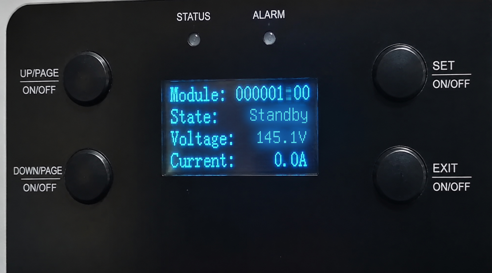
Controller Module 1 is reporting fault code 000000100. According to the fault code description, this indicates a battery undervoltage alarm; therefore, we simply need to inspect the battery input.
一. IGBT Fault
1. It may be a false alarm. Restart the controller and check whether the alarm can be cleared.
2.Contact the manufacturer for repair.二. Battery Overvoltage
1. Measure the output voltage and check whether it is higher than the controller equalization charging voltage.If it is higher, reduce the busbar voltage of the power cabinet or increase the equalization charging voltage of the controller.
2. If there is a significant difference between the measured output voltage and the voltage displayed on the screen, the sampling accuracy may be abnormal. Contact the manufacturer for repair.三. PV Overvoltage
1. Measure the PV input voltage and check whether it exceeds the maximum input voltage of the controller.If it exceeds the limit, reduce the number of PV modules connected in series.
2. If there is a significant difference between the measured PV input voltage and the voltage displayed on the screen, the sampling accuracy may be abnormal. Contact the manufacturer for repair.
四. Charging Overcurrent
1. Check whether the maximum charging current value in the controller settings matches the rated maximum charging current of the controller model.If they do not match, modify the setting to the corresponding value.
2. Contact the manufacturer for repair.五. Ambient Overtemperature
1. Install an air conditioner or apply other cooling methods to reduce the ambient temperature.
2. Reduce the number of PV modules to decrease the PV input power.
3. Contact the manufacturer for repair.六. Heat Sink Overtemperature
1. Install an air conditioner or apply other cooling methods to reduce the ambient temperature.
2. Turn off the controller and restart it after the controller has cooled down.
3. Contact the manufacturer for repair.七. Battery Undervoltage
1. Measure the output voltage.If the output voltage is low and consistent with the busbar voltage, check the voltage of the switching power supply cabinet.
2. Measure the output voltage.If the output voltage is significantly lower than the busbar voltage, check whether the fuse in the switching power supply cabinet is blown.
3. Contact the manufacturer for repair.八. Battery Overvoltage (Hardware)
Contact the manufacturer for repair.九. Command Shutdown
The controller has been shut down through a communication command.
Restore operation by sending a power-on command through the communication interface. - 22.How to choose a MPPT controller?
-
A: MPPT controller is related to the solar panels total power and battery system voltage. According to the calculation formula P=U*I, you can get the MPPT controller rated current. For example, the solar panels total power is 2000W, battery system voltage is 48V, that MPPT controller rated current I=2000W/48V=41.6A, so choose MPPT controller is 48V 50A which need greater than 41.6A. For details please refer to the calculation formula in our website.
- 23.Troubleshooting Common Issues with IPANDEE Combiner Box Adapters
-
I. Adapter module data shows values only for input power:
1) Check that the serial number on the adapter matches the connected module number (e.g., Adapter No. 1 must connect to Module 1).
2) Open the adapter's back panel and reset the DIP switches to match the adapter's marked serial number.
3) Carrier signal interference caused by the environment is normal and will resolve itself; the presence of input power indicates the controller is operating correctly.
II. Adapter not generating power:
1) Ensure wiring is correct, with no reversed or incorrect connections.
2) Check if the fuse in the combiner box junction box is blown or disconnected.
3) The PV input voltage must be lower than the busbar voltage.
4) The adapter output voltage should be higher than the busbar voltage.
5) If the adapter or combiner box is damaged, contact the manufacturer for troubleshooting.
III. Display unit not lighting up:
1) Restart the combiner box and observe if it returns to normal operation.
2) Check if input and output voltages are normal, and ensure output cables are properly connected and not reversed.
3) Check the voltage at the power input terminals of the display unit's upper terminal block; if the voltage is abnormal, check for loose connections in the display unit's power supply line.
4) Check if the fuse in the switching power supply cabinet is blown (test for continuity using a multimeter).
5) If the display unit is damaged, contact the manufacturer for troubleshooting.
IV. Display screen shows abnormal module output voltage:
1) Verify correct wiring (no incorrect or reversed connections) and ensure the adapter serial number matches the connected module number.
2) Use a multimeter to measure the voltage at the MC4 connectors of the cable running from the combiner box to the adapter; ensure terminals are securely crimped and there are no loose connections.
3) Measure the voltage at the combiner box junction box terminals; if there is no voltage, check the fuse for continuity.
4) Swap the module's cable to another module position and update the adapter address accordingly to see if the issue resolves.
5) Contact the manufacturer for troubleshooting.
V. Platform not coming online:
1) Refer to the gateway indicator light guide to check if the gateway status is normal.
2) Check the A/B lines on the gateway, electricity meter, and combiner box for loose connections or reversed polarity.
3) Reinstall the SIM card and restart the gateway to test.
4) SIM card issue (insufficient balance or damage); replace the SIM card to test.
5) Check that the antenna is properly connected and verify that the local network signal for the SIM card's carrier is strong.
6) Contact the manufacturer for troubleshooting.
VI. Low power generation:
1) Poor weather or weak sunlight resulting in low PV panel power output.
2) PV panels are shaded, aging, or covered with dust.
3) System load is low; the PV system is already fully supplying the load, replacing grid power.
4) Contact the manufacturer for troubleshooting.
- 24.How to make maximum efficiency use of the solar panels in series-parallel connection?
-
A: The total open circuit voltage(Voc) of solar panel in series cannot exceed MPPT controller maximum PV input Voc, as well the total power voltage(Vmp) cannot less than MPPT controller charging voltage.
The details series-parallel connection please refer to the user manual “ Serial Connection(string) of PV Modules”, you also can refer to the calculation formula in the website. - 25.Troubleshooting Common Issues with IPANDEE Controllers
-
I. Controller shows no alarm but is not charging;
Possible causes:
1) Battery is fully charged; controller is in standby mode.
2) Incorrect battery type selection or incorrect charging parameters.
3) PV input voltage is lower than the controller's startup voltage.
4) Controller malfunction.
Troubleshooting steps:
1) Verify that the battery type selected on the controller matches the actual battery type.
2) Confirm whether the battery voltage displayed on the controller has reached the saturation voltage and if the battery is fully charged.
3) Use a multimeter to measure the PV input voltage; check if it matches the PV voltage displayed on the controller and exceeds the controller's charging startup voltage.
II. Controller does not turn on; screen is blank:
Possible causes:
1) Battery and PV connections are loose or reversed;
2) Battery voltage and PV voltage are too low;
3) Controller is damaged or malfunctioning.
Troubleshooting steps:
1) Check the wiring at the controller's BAT and PV terminals for loose or incorrect connections.
2) Use a multimeter to measure the voltage at the BAT and PV terminals; verify that the BAT and PV voltages meet the controller's supported voltage specifications.
3) If the conditions above are met but the screen remains blank, the controller is likely faulty.
III. Controller shows a red light; device alarm triggered:
Possible causes:
1) Battery and PV cables are loose or incorrectly connected;
2) Battery voltage or PV voltage is too high or too low;
3) Incorrect battery system parameter selection;
4) Controller is damaged or malfunctioning.
Troubleshooting steps:
1) Check the wiring at the controller's BAT and PV terminals for loose or incorrect connections.
2) Measure the battery and PV voltages to ensure they match the values displayed on the screen and fall within the safe operating range (i.e., not exceeding over-voltage protection limits or dropping below under-voltage limits).
3) Verify that the battery system and type selected on the controller match the actual connected battery system and type.
IV. No output voltage at the load output terminal:
Possible causes:
1) Controller load setting is not enabled;
2) Incorrect load wiring connections;
3) Battery is in an over-voltage or under-voltage state;
4) Controller is damaged;
Troubleshooting methods:
1) Set the controller load to "always-on" mode and measure whether there is voltage output at the load terminal.
2) Check the load terminal wiring for reverse polarity or short circuits.
3) Check the battery voltage status displayed on the controller to see if it is in an over-voltage or under-voltage state.
4) If the controller is damaged, contact the manufacturer for assistance.
V. Displayed values do not match actual measured values:
Possible causes:
1) Minor sampling deviation; this is normal sampling error.
2) Sampling has not been calibrated for a long time, resulting in deviation;
3) Loose sampling wire;
4) Controller sampling circuit is damaged;
Troubleshooting methods:
1) If the difference between the displayed value and the actual measured value is small, it is a normal phenomenon (sampling error).
2) If the difference is significant but the displayed value fluctuates correctly (rising or falling) in sync with the actual value, use the host computer software to calibrate the displayed value.
3) Check if the screen ribbon cable is loose; unplug and reconnect the controller display cable.
4) If the controller is damaged, contact the manufacturer for assistance.
VI. Input voltage drops to a level close to the battery voltage; no charging occurs:
Possible causes:
1) Weak photovoltaic (PV) energy;
2) PV input voltage is close to the battery voltage;
3) Controller is damaged;
Troubleshooting methods:
1) Observe whether the phenomenon persists on a sunny day.
2) Increase the PV voltage; the PV voltage needs to be at least 5V higher than the battery voltage.
3) If the controller is damaged, contact the manufacturer for assistance.
VII. Controller cannot connect to the host computer:
Possible causes:
1) Incorrect connection settings;
2) Software not run as administrator or host computer drivers not installed;
3) Damaged computer port or connection cable; 4) Controller communication circuit damaged.
Troubleshooting methods:
1) Check if the COM port number, baud rate, and address bits are correct.
2) Reinstall the host computer drivers, run the software as an administrator, and test the connection again. 3) Try connecting using a different computer port or data cable.
4) If the controller's communication function is damaged, contact the manufacturer for assistance.