


How to solve common problems in off-grid photovoltaic system design?
1, components,InverterWhen the battery is designed, it must be matched. No one can be too big or too small. When designing a newbie, the power consumption will be calculated too much. For example, 1P air conditioner runs for 12 hours, counts as 10 degrees, and 300W refrigerator runs for 24 hours. , calculated as 7.2 degrees of electricity, resulting in excessive battery capacity, system cost is too high. When designing the battery capacity, it is best to fill the specifications in 2 days.
2,Off-grid photovoltaic power generationThe system output is connected to the load. The voltage and current phases and amplitudes of each inverter output are different. The inverter does not support the output terminals in parallel. Do not connect the inverter output terminals together.
3. The load is a load such as an elevator. It cannot be directly connected to the output of the inverter. Because the elevator is falling, the motor reverses, and a back electromotive force is generated. When entering the inverter, the inverter is damaged. If an off-grid system is necessary, it is recommended to add a frequency converter between the inverter and the elevator motor.
4. The photovoltaic micro-grid system with the complementary input of the mains needs to be insulated from the components. If the components have leakage current to the ground, they will be transmitted to the mains, causing the leakage switch of the mains to trip.
5. The voltage of the component and the voltage of the battery should be matched. The PWM type controller solar module and the battery are connected by an electronic switch. There is no inductance and other devices in the middle. The voltage of the component is between 1.2 and 2.0 times of the voltage of the battery. It is a 24V battery, the input voltage of the component is between 30-50V, the MPPT controller has a power switch tube and an inductor circuit in the middle. The voltage of the component is between 1.2-3.5 times of the voltage of the battery. If it is a 24V battery, The component input voltage is between 30-90V.
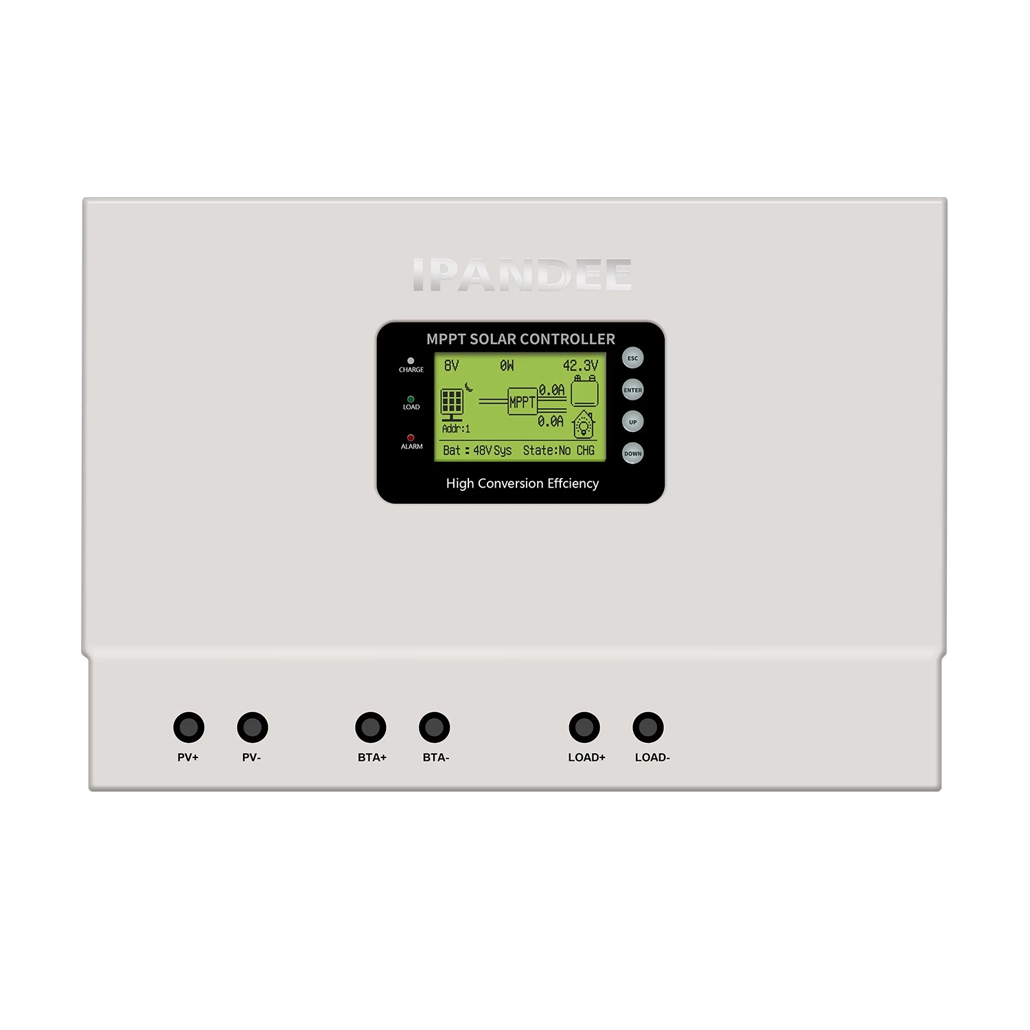
6, the output power of the component and the power of the controller should be similar, such as a 48V30A controller, the output power is 1440VA, the power of the component should be around 1500W. When selecting a controller, first look at the voltage of the battery, and then divide the power of the component by the voltage of the battery.ControllerOutput current.
7. The charging current of the battery is generally 0.1C-0.2C, and the maximum is not more than 0.3C. For example, a lead-acid battery 12V200AH, the charging current is generally between 20A and 40A, the maximum can not exceed 60A; the discharge current of the battery is generally 0.2. C-0.5C, the maximum does not exceed 1C, 1 section 12V200AH lead-acid battery, the maximum output power does not exceed 2400W, different manufacturers, different models, the specific values are not the same, the design should ask the manufacturer for instructions.
Disclaimer: The content is partly from the internet. In order to pass on more information, it does not mean agreeing to its views or confirming its description. Article content is for reference only. If there is any infringement, please contact in time.
