


Controller in photovoltaic power station
The controller is an important part of the photovoltaic power station. When designing the controller, it must take into account whether the controller can optimize the control and management of the power conversion of the photovoltaic power station and the charging of the battery. Only by choosing the right type can we improve the safety and reliability of PV power plants and provide users with better power quality.
Independently operating photovoltaic power plants typically consist of photovoltaic cell arrays, battery packs, controllers, inverters, low voltage transmission lines, and user loads. The battery plays the role of the storage box to regulate the electric energy: when the energy generated by the solar cell is excessive, the battery pack stores excess electric energy; when the system generates insufficient power or the load uses a large amount of electricity, the battery pack replenishes the load to the load. And keep the supply voltage stable. The controller is the control part of the photovoltaic power station: it continuously switches and adjusts the working state of the battery pack according to the change of the sunshine intensity and the load, so that it alternately operates under various working conditions such as charging, discharging or floating charging. Thereby ensuring the continuity and stability of the operation of the photovoltaic power station; by detecting the state of charge of the battery pack, issuing a command to continue charging, stopping charging, continuing to discharge, reducing the amount of discharge or stopping the discharge, protecting the battery pack from overcharging and In addition, the controller also has a variety of protection and monitoring functions. The controller is the central power supply of the entire power station. Its operating status directly affects the reliability of the entire power station. It is the key to special attention during system design, production and installation. section.
ControllerBasic principle of controlling charge and discharge
1 battery charging control
Different batteries have different charge and discharge characteristics, so different control strategies are also required. Here, the lead-acid battery is taken as an example to illustrate the working principle of the controller.
There are many ways to charge lead-acid batteries, such as floating charge, current-limiting constant-voltage charge, and incremental voltage charging. The most used one is the current limiting constant voltage charging. The terminal voltage variation of the battery during charging is shown on the left side of the figure below.
The charging process is divided into three phases. In the first stage, the sulfuric acid formed in the micropores of the active material suddenly increases, and it does not reach the outside of the plate. Therefore, the battery potential increases and the battery terminal voltage rises faster (OA segment); the second stage, along with the active material micropores The rate of increase in the specific gravity of sulfuric acid and the rate of outward diffusion gradually become balanced, so the voltage at the battery terminal rises slowly (AB segment); in the third phase, the current causes a large amount of water in the battery to decompose, and a large amount of water is generated on the two plates. Gas, these gases are poor conductors and can increase the internal resistance of the battery, and the battery terminal voltage continues to rise but the rate of rise is significantly slower (CD segment). After the third stage, if the battery is continuously charged, it will be damaged due to overcharging, which will affect the service life of the battery. According to this principle, the voltage measurement and voltage comparison circuit is set in the controller. By monitoring the voltage value of the D point, it can be judged whether the battery should end the charging; this control mode is the voltage type charging control, and the comparator setting D The point voltage is called the "threshold voltage" or voltage threshold.
2 basic principle of battery discharge control
The discharge process of lead-acid batteries. Similar to the charging process, the terminal voltage of the battery during the discharge process is also composed of three stages. In the first stage, when the discharge starts, the battery terminal voltage drops rapidly (OA segment) in a short time; in the second phase, the battery terminal voltage drops slowly (AC segment); in the third phase, the battery terminal voltage is fast in a very short time. Lower (CD segment). It can be seen that during the discharge process, the longer the second phase, the higher the average voltage and the better the voltage characteristics. According to this principle, a voltage measurement and voltage comparison circuit is set in the controller. By detecting the voltage value at point D, it can be judged whether the battery should end the discharge. This control mode is voltage type discharge control, and the voltage at point D is called " Threshold voltage" or "voltage threshold".
Controller type and characteristics
Currently used photovoltaic systemsCharge and discharge controllerThere are multiple types of series bypass and pulse type, each of which has its own characteristics, and the application objects are not the same.
1 series controller
The controller detection circuit monitors the battery terminal voltage. When the battery full-charge voltage reaches the corresponding threshold, the serial controller switching element cuts off the battery charging circuit, and the battery stops charging; when the battery terminal voltage drops to the voltage threshold for restoring charging, The switching element here switches on the battery charging circuit and resumes charging of the battery. The advantages of the series controller are small size, simple circuit, and low price. However, since the control power transistor has a tube voltage drop, a large energy loss is caused when the charging voltage is low. In addition, when the control element is disconnected, the input voltage will rise to the level of the open circuit voltage of the power generating unit, so the series controller is suitable for photovoltaic power generation systems below kilowatt level.
2 bypass controller
The controller monitoring circuit monitors the battery terminal voltage. When the battery full-charge voltage reaches the corresponding threshold, the switching element turns on the energy-consuming load, disconnects the battery circuit, and the over-charge current is transferred to the energy-consuming load by the switching element, which will be redundant. The power is converted to heat. When the battery terminal voltage drops to the voltage threshold for restoring charging, the switching element disconnects the energy-consuming load and simultaneously turns on the battery charging circuit. The bypass controller is simple in design, inexpensive, and has a small charging loop loss, but requires a large current-carrying capability of the control element. The simple bypass controller is mainly used for photovoltaic power generation systems below kilowatt level, and the high standard bypass controller can also be used for larger power photovoltaic power plants. In a square array in which a plurality of sets of solar panels are connected in series, adjusting the charging voltage of the battery by bypassing one or more battery panels in the series is called partial bypass control, and the circuit principle of the partial bypass controller is as shown in the following figure. Show.
3 multi-level controller
The core component of a multi-stage controller multi-circuit is a charge signal generator controlled by a charging voltage. The multi-stage controller automatically sets different charging currents according to the state of charge of the battery: when the battery is in an under-filled state, the simulated current is allowed to flow into the battery pack; when the battery pack is nearly full, the controller consumes some The output power of the policy is to reduce the current flowing into the battery; when the battery pack is gradually approaching full charge, the "turbulent" charging is gradually stopped. Applying the principle of multi-level controller to a photovoltaic power plant composed of multiple sub-squares can form multi-channel control, and the current generated by none of the sub-matrices becomes each charging current step of multi-stage control. According to the state of charge of the battery pack, the controller turns on the input of each sub-matrix in turn, or can switch the input of each sub-matrix to the energy-consuming load one by one, thus generating charging currents of different sizes. As shown below. In order to make full use of solar energy, the excess energy of the sub-array can also be transferred to the secondary power load.
4 pulse controller
The core component of the pulse controller is a charging pulse generator modulated by a charging voltage. The controller operates in a chopping manner to pulse charge the battery. When the charging starts, the pulse controller charges with pulse width. As the charging voltage rises, the charging pulse width gradually narrows, and the average charging current also gradually decreases. When the charging voltage reaches the preset level, the charging pulse width becomes 0, charging. termination. The pulse controller has reasonable charging mode and high efficiency, and is suitable for photovoltaic power plants with high power.
The pulse width modulation (PWM) controller has the same basic principle as the pulse controller. The main difference is that the charging pulse generator is designed as a charging pulse width modulator, so that the instantaneous variation of the charging current of the charging pulse is more in line with the current state of charge of the battery. The most ideal state of charge is that the charging current of the battery is acceptable. The PWM controller with AC-DC conversion can also realize the maximum power tracking function of the PV power plant. Therefore, the pulse width modulator can be used in large-scale photovoltaic power plants. The disadvantage is that the pulse width modulation controller itself will bring a certain loss (about 4% to 8%).
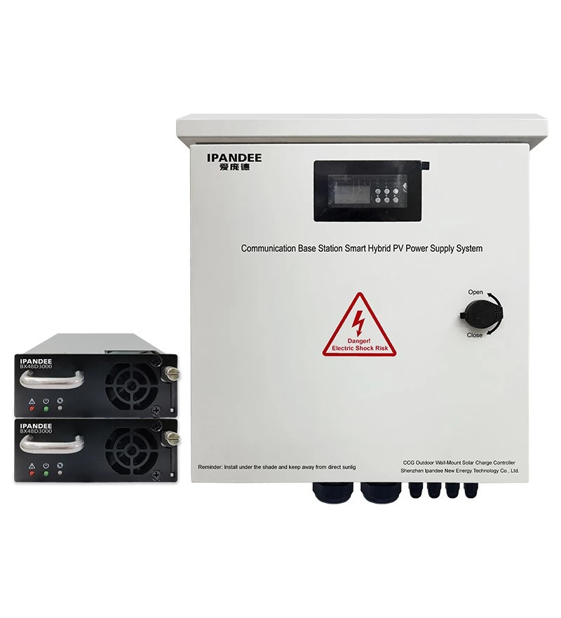
We are a professional MPPT solar charging controller manufacturer, off-grid solar controller, solar charging controller supplier, solar charging controller - inverter factory
Disclaimer: The content is partly from the internet. In order to pass on more information, this does not mean agreeing to its views or confirming its description. Article content is for reference only.
