


- 浏览分类
- EMMPT48 series MPPT solar charge controller
- The Explorer-NS series MPPT solar charge controlle
- MPPT solar charge controller eSmart4
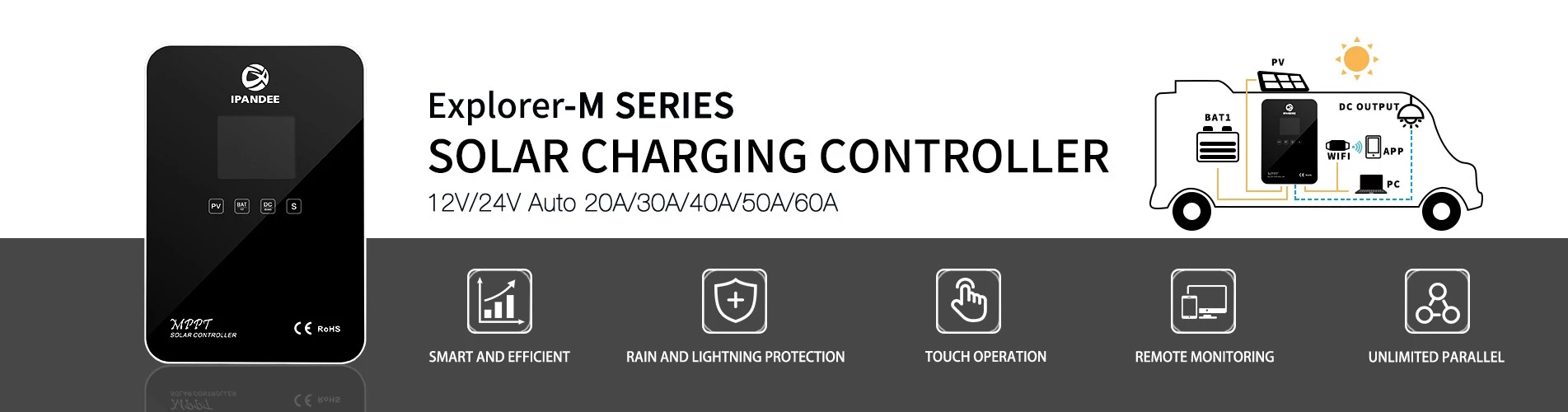
- EXPLORER-M MPPT Solar Smart Digital Controller
- EXPLORER MPPT太阳能智能数字控制器
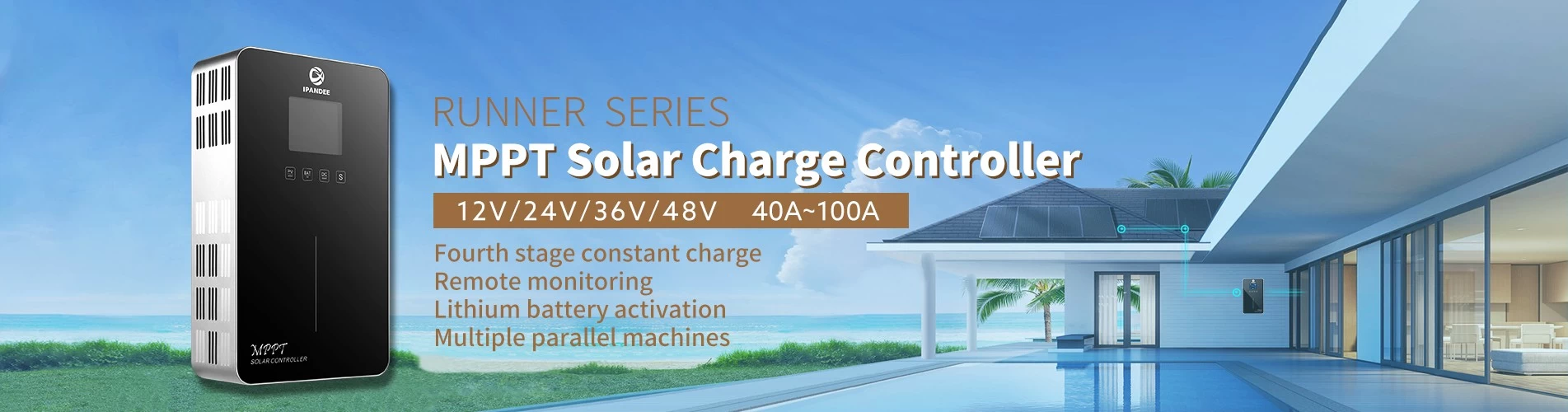
- RUNNER MPPT太阳能智能数字控制器
- GALAXY大功率系列MPPT太阳能控制器
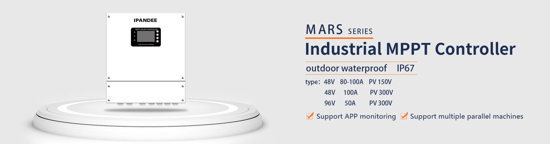
- MARS户外系列 MPPT太阳能控制器
- eSMART系列MPPT太阳能控制器
- MASTER系列MPPT太阳能控制器
- 配件
- (已下架)WISER系列MPPT太阳能控制器
- (已下架)变频器SP系列350W-20000W
- (已下架)
- (已下架)I-Panda SPC系列变频器
- 认证
-


")


- 订阅
-
获取有关新产品的电子邮件更新

- 联系我们
-
电话:+ 86-755-23091101&+ 86-755-23091100
传真:+ 86-755-23091102
信息:info@ipandee.com
地址:深圳市龙岗区南湾街道布澜路31号李朗软件园A2栋2楼
中国邮政编码:518000 现在联系
- 跟着我们
-
-
为什么逆变器的启动电压比最低电压高?
在光伏并网逆变器中,有一个参数比较奇怪,那就是逆变器输入启动电压。 这个电压比最低工作电压要高30V左右,如单相逆变器,MPPT工作电压是70V到5... -
怎么解决光伏逆变器交流过压问题?
现在光伏并网发电越来越普及,寻常的百姓家也能实时见到光伏电站的身影了。然而,对老百姓来讲,对光伏并网系统尤其是并网逆变器仍然没有像对电视... -
改进的正弦波和纯正弦波逆变器之间的区别
本文介绍改进的正弦波和纯正弦波逆变器之间的区别 ModifiedSine纯波:最常见的通用逆变器可用于“修正正弦波”多种类型,与纯正弦波模型相比,通... -
欧洲首家废弃光伏板回收工厂
太阳能电池板的使用寿命为20年至30年。随着前几年全球太阳能制造业的大量生产,若干年后,全世界将掀起一波光伏板的“报废潮”,到2050年甚至会达... -
全球十大光伏逆变器企业
逆变器又称电源调整器,根据逆变器在光伏发电系统中的用途可分为独立型电源用和并网用二种。根据波形调制方式又可分为方波逆变器、阶梯波逆变器、... -
电网停电时逆变器为什么要停止工作?
有些人在安装光伏系统时,会抱着一种“即使电网停电,如果有太阳,自己家也能用上电”的心态,现实情况是,电网停电时,自己家的光伏发电系统只会... -
MPPT功能和不带MPPT功能的太阳能逆变器有什么区别?
MPPT控制器利用最大功率点跟踪技术从太阳能阵列中提取最大的功率为蓄电池充电。最大功率点跟踪方式完全自动,不需要用户调整。在阵列最大功率点随... -
科学家发现沙子可造太阳能电池硅材料
据日本共同社11月6日报导,日本东京大学客座教授鲤沼秀臣等人与阿尔及利亚奥兰科学技能大学打开共同研究,发现可以用沙漠的沙子低价制作太阳能电... -
国内储能市场竞争格局
储能作为一个新式的市场,为我国数量很多的电池厂商和逆变器厂商带来了拓展新事务、改动原有事务职业地位的时机。 2018年以来,快速开展的我国储... -
如何建造光伏电站
1.什么样的屋顶适合于安装光伏发电厂? 最适合安装国内光伏屋顶的是农村别墅:屋顶状况良好,没有受阻。你可以看看屋顶周围有障碍,如果照明条件...
-
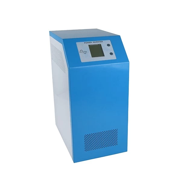
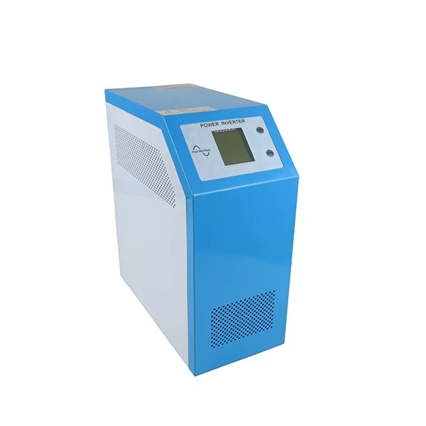
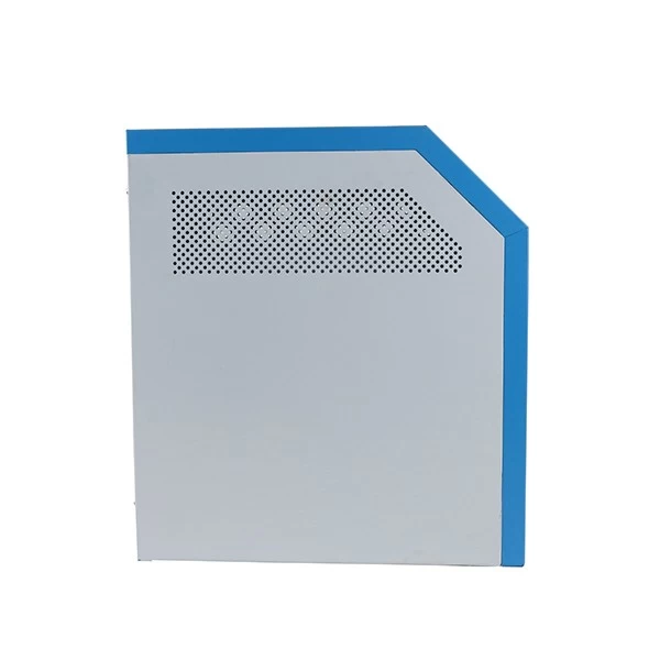
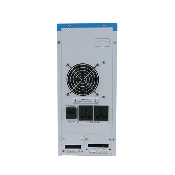
I-P-SP China factory DC AC Power 10KW
- Application
- 1、Back-up UPS system for industrial, commercial, household,etc
- 2、Removable power and standby power for areas that are lack of utility.
- 3、Off-grid solar or wind power system
- 3.1、Off-grid solar or wind power system
- 3.2、AC first Off-grid solar or wind power system
- 3.3、DC first Off-grid solar or wind power system
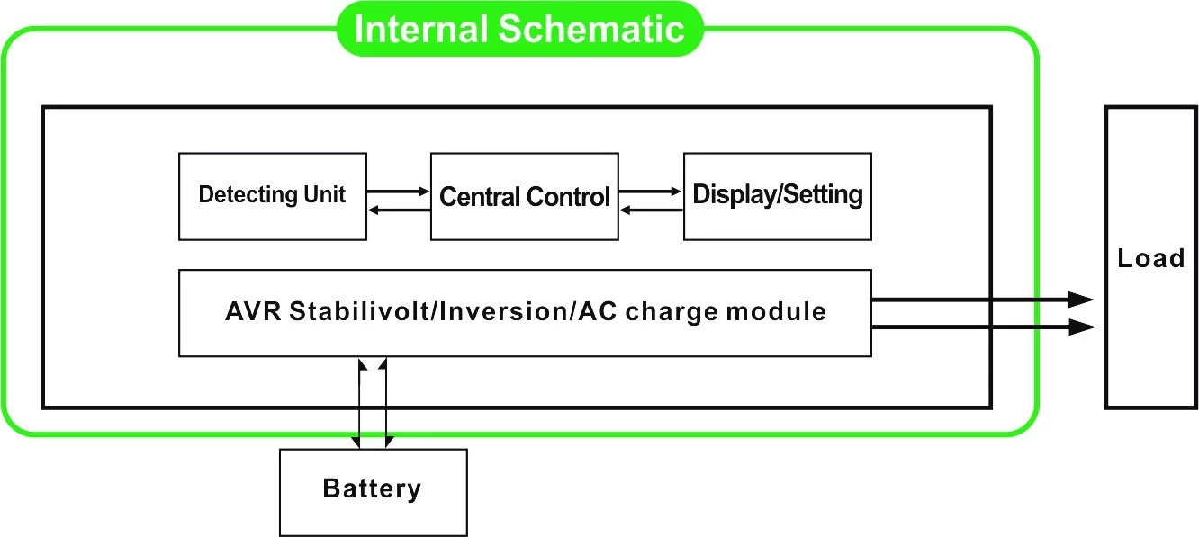
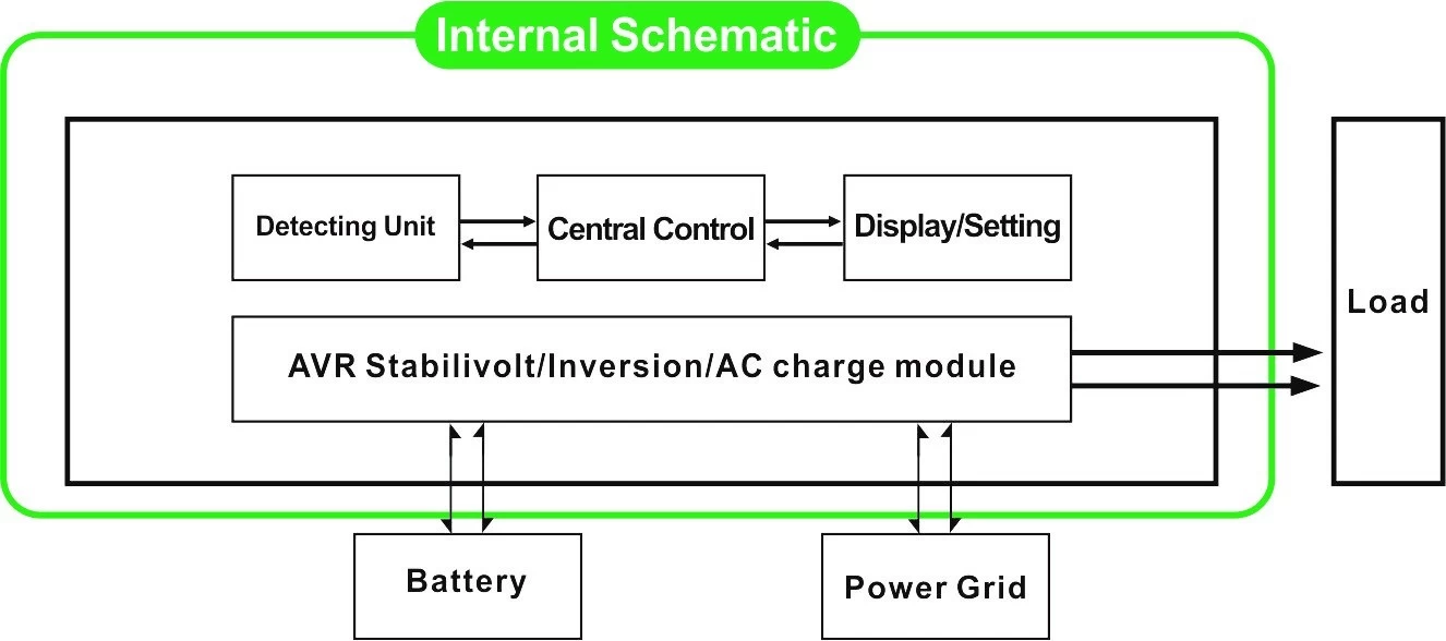
Introduction
In DC/AC inversion mode, users can set this series of inverters to normal working mode or sleep mode. In utility mode, it has Auto Voltage Regulation (AVR) function, utility charging function (AC first model) and UPS function. This multifunctional low frequency pure sine wave inverter has the advantages of stable quality, strong load-carrying ability and long service life. It also can work in poor environment. It is the second generation of our low frequency pure sine wave inverter I-P-XD-series.
Features
1、pure sine wave output, full power
2、CPU control,intelligent control,modular design
3、LCD display various parameters
4、Multifunction design (AVR, UPS), extra charger is not needed and electric appliances can be protected.
5、External battery connection, it’s convenient for users to expand use time and back-up power time
6、With super load carrying ability and high load capacity, this series of inverters can not only drive resistance load; but also various kinds of inductive loads, such as motor, air conditioner, electric drills, fluorescent lamp, gas lamp.
7、Low frequency circuit design, stable quality, low failure rate and long service life (under proper operation, it can last at least 5 years)
8、Perfect protection: low voltage protection, high voltage protection, over temperature protection, short-circuit protection, overload protection, alarm alert
9、CE / EMC / LVD/ RoHS Approvals
10、Two years warranty, life-long technical support
Function
1、DC to AC inversion function in inversion mode (only connected with batteries and loads) ,users can set it to normal working mode or sleep mode
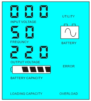
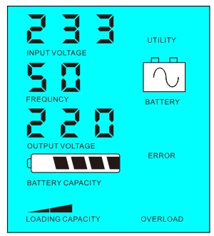
1.1、Normal working mode:FREQUNCY in the LCD display is set to 01. No matter it’s connected AC loads or not, the inverter always convert DC to AC. It’s ready to supply power to the AC loads. In this mode, the LCD will display output voltage as bellow:
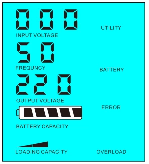
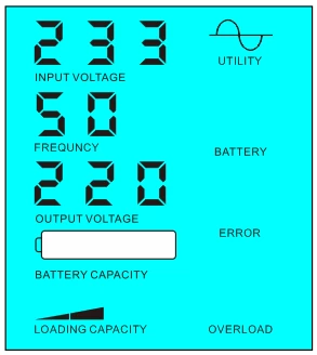
1.2、Sleep mode:FREQUNCY in the LCD display is set as 02.If the power of the connected AC loads is lower than 5% of the inverter’s rated power, there will be no output from the inverter. Only the chip of inverter is working. The power consumption of the inverter is only 1-6W. The LCD shows the output voltage 0. If the power of the connected loads is over 5%,then the inverter will automatically convert DC to AC to supply power for the loads within 5s. The LCD shows the output voltage. As shown below:
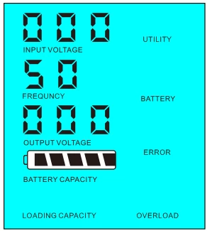
 Load’s power<5% of inverter’s rated power Load’s power>5% of inverter’s rated power
2、UPS function When the inverter is connected to battery and utility, users can set it to utility first (AC first) battery standby mode or battery first (DC first)utility standy mode.
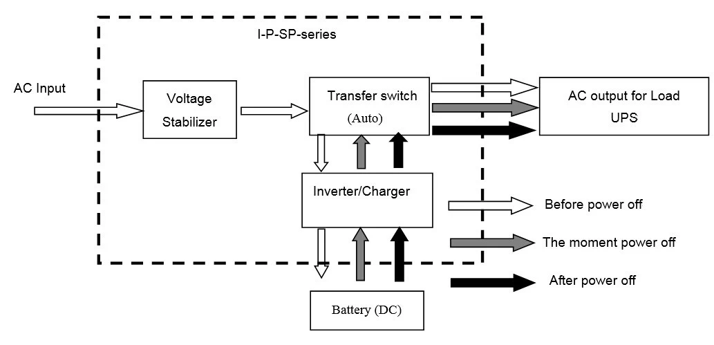
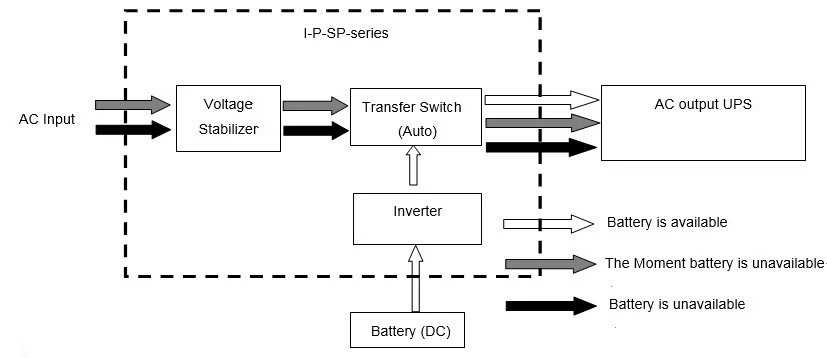
2.1、Utility first (AC first) battery standby mode : FREQUENCY in the LCD display is set to 01. When utility and battery are connected to the inverter, utility will supply power to the loads prior. When utility is cut off, the battery will automatically continue to supply power via power inverter.
Steps are as follows:
Step 1: When utility is available, it will drive the loads directly after voltage being stabilized and at the same time charge batteries via power inverter .
Step 2: When utility is cut off, the inverter will convert DC to AC automatically to ensure uninterrupted power supply within 5ms.
Step 3: When utility is available again, inverter will automatically transfer to utility supplying power to loads and charge batteries via power inverter at the same time.
See Workflow as below.
LCD displayed as bellow:
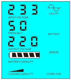
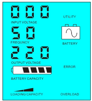
Utility supply power and charge battery Utility is unavailable, battery supply power
2.2、Battery first (DC first)utility standby UPS mode: FREQUENCY in the LCD display is set as 03. When utility and battery are connected to the inverter, battery will supply power to the loads prior to utility. When battery capacity is not enough, utility will continue to supply power automatically.
Steps are as follows:
Step 1: When battery is available, it will drive the AC loads via power inverter.
Step 2: When battery does not have enough power, it will automatically transfer to utility supplying power to the loads
Step 3: After the battery is fully charged (e.g. by solar or wind charge controller), it will automatically transfer to battery supplying power to the loads via power inverter.
See Workflow as below
LCD displayed as bellow:
Battery is available Battery is not available,utility supply power
Parameter
|
Model Parameter |
15kVA |
|
|
Rated Output Capacity |
10KW |
|
|
Peak Power |
20KW |
|
|
Battery Voltage(DC) |
96V/192V(optional) |
|
|
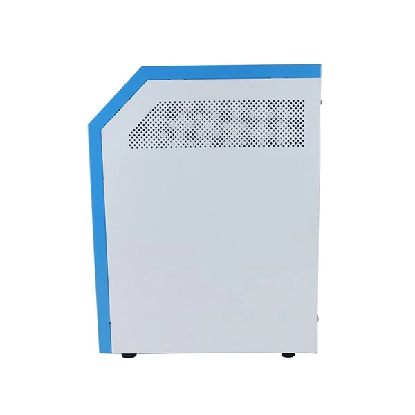
Size W×D×H(mm) |
420*260*605 |
|
|
Packing Size W×D×H(mm) |
440*280*625 |
|
|
Net Weight (kg) |
85 |
|
|
Gross Weight (kg) |
95 |
|
|
General Parameter |
||
|
Working Mode |
1 |
Utility first (AC first) battery standby mode |
|
(Setting) |
2 |
Sleep Mode,no utility,load’s power higher than 5% of inverter rated output power,it will start to work automatically |
|
|
3 |
Battery first (DC first)utility standby UPS mode |
|
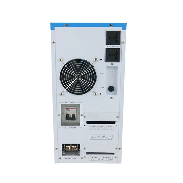
AC Input |
Voltage |
220V±35% or 110V+35%(optional) |
|
Frequency |
50Hz±3% or 60Hz±3% (optional) |
|
|
AC Output |
Voltage |
220V±3% or 230V±3 or 240V±3% or 100V±3% or 110V±3% (optional) |
|
Frequency |
50Hz±0.5 or 60Hz±0.5 (optional) |
|
|
Battery charge |
AC Charge Current |
0~15A |
|
Charge Time |
Depend on battery capacity and quantity |
|
|
Battery Protection |
Automatic detection, Charge and discharge protection,Intelligent Management |
|
|
Display |
Display Mode |
LCD |
|
Display Information |
Input voltage,output voltage,output frequency,battery capacity,Load condition,Status Information |
|
|
Output Wave Type |
Pure sine wave output,Total Harmonic Distortion THD≤3 |
|
|
Overload Ability |
>120% 1 min,>130% 10s |
|
|
Power Consumption |
Sleep Mode |
1~6W |
|
Normal Mode |
1~3A |
|
|
Conversion Efficiency |
80%~90% |
|
|
Transfer Time |
<5ms (AC to DC / DC to AC) |
|
|
Protection |
Overload ,Short-circuit,High input voltage,Low input voltage,Overheat |
|
|
Environment |
Temperature |
-10℃~50℃ |
|
Humidity |
10%~90% |
|
|
Altitude |
≤4000m |
|
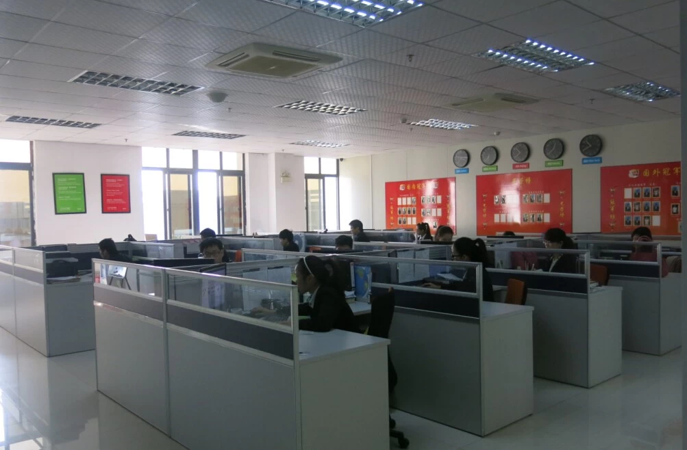
We have our own professional inverter and controller R&D team and we
provide technical support and OEM ODM service.
Others
Please see the outline of the design,technical documents,user manuals,product brochures, etc.Research and development department made 2th edition on May 5, 2014.
Company


- 其他产品


